이중화
카테고리: duplexing
태그: 이중화
이중화
- 원인
- 프레임을 전달할 수 있는 경로가 2개 이상 발생 함 → 2이상의 port에서 같은 목적지를 학습
- 해결책
- 최적의 경로만 활성화하고 다른 경로를 막아 놓았다가 장애가 발생하였을 때 백업 경로를 사용 함
- 최적의 경로와 경로의 문제를 주기적으로 Data를 주고 받아서 판단 함
STP
- STP (Spanning Tree Protocol)
- Switch를 이중화 하였을 때 발생하는 Loop 문제를 해결하기 위해 사용 됨
- Switch에서 기본으로 동작 함
- 목적지에 대한 경로가 2개 이상일 때 한 경로 남겨두고 다른 경로를 끊어서 Loop를 방지 함
- 사용중인 경로의 장애를 감지했을 때 백업 경로를 활성화 하여 가용성을 보장 함
- 신장 트리(Spanning Tree) 알고리즘을 사용하여 Loop 방지를 위한 최적의 경로를 구함
PVST
- PVST(Per VLAN Spanning Tree)
- STP가 기본적으로 VLAN 수와 상관없이 동작함으로 특정 루트 브릿지에 트래픽이 몰리며, 특정 브릿지는 사용되지 않고 낭비되는 문제점이 발생
- 각 VLAN 별로 Spanning Tree 동작함으로 써 VLAN 별 최적 경로 및 부하 분산 효과 발생
- 각 VLAN 별로 루트 스위치를 따로 지정
실습
-
구성도
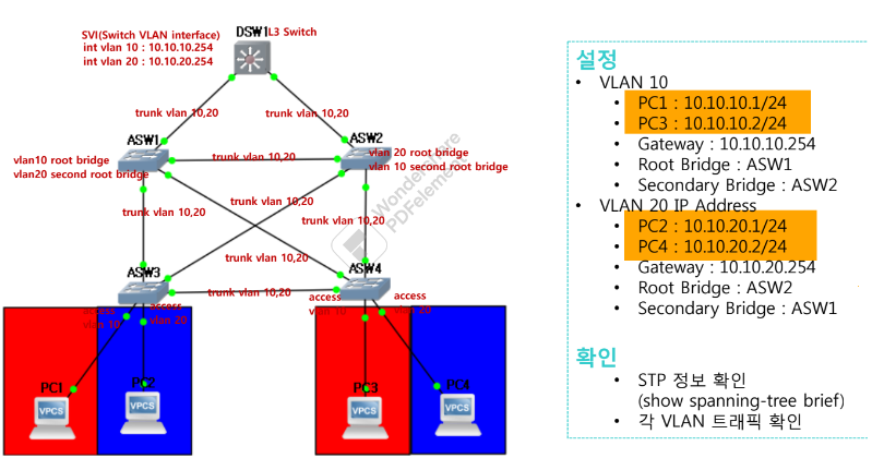
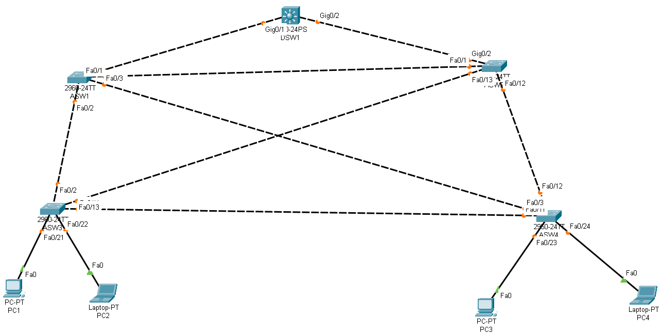
-
각 Switch 별 VLAN 설정
DSW1(config)#vlan 10 DSW1(config)#vlan 20 ASW1(config)#vlan 10 ASW1(config)#vlan 20 ASW2(config)#vlan 10 ASW2(config)#vlan 20 ASW3(config)#vlan 10 ASW3(config)#vlan 20 ASW4(config)#vlan 10 ASW4(config)#vlan 20 -
DSW1 - SVI 에 주소 입력
DSW1(config)#int vlan 10
DSW1(config-if)#ip address 10.10.10.254 255.255.255.0
DSW1(config-if)#no sh

DSW1(config)#int vlan 20
DSW1(config-if)#ip address 10.10.20.254 255.255.255.0
DSW1(config-if)#no sh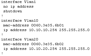
-
ASW3,4 에 PC1~4 까지 연결된 인터페이스에 ACCESS port 설정
ASW3(config)#int f0/21 ASW3(config-if)#switchport mode access ASW3(config-if)#switchport access vlan 10 ASW3(config)#int f0/22 ASW3(config-if)#switchport mode access ASW3(config-if)#switchport access vlan 20 ASW4(config)#int f0/21 ASW4(config-if)#switchport mode access ASW4(config-if)#switchport access vlan 10 ASW4(config)#int f0/22 ASW4(config-if)#switchport mode access ASW4(config-if)#switchport access vlan 20 -
각 ASW , DSW 에 Trunk 설정
ASW3(config)#int f0/2 ASW3(config-if)#switchport mode trunk ASW3(config-if)#switchport trunk allowed vlan 10,20 ASW3(config)#int f0/3 ASW3(config-if)#switchport mode trunk ASW3(config-if)#switchport trunk allowed vlan 10,20 ASW3(config)#int f0/12 ASW3(config-if)#switchport mode trunk ASW3(config-if)#switchport trunk allowed vlan 10,20 ASW3(config)#int f0/3 ASW3(config-if)#switchport mode trunk ASW3(config-if)#switchport trunk allowed vlan 10,20 ASW3(config)#int f0/4 ASW3(config-if)#switchport mode trunk ASW3(config-if)#switchport trunk allowed vlan 10,20 ASW3(config)#int f0/11 ASW3(config-if)#switchport mode trunk ASW3(config-if)#switchport trunk allowed vlan 10,20 ASW2(config)#int f0/4 ASW2(config-if)#switchport mode trunk ASW2(config-if)#switchport trunk allowed vlan 10,20 ASW2(config)#int f0/12 ASW2(config-if)#switchport mode trunk ASW2(config-if)#switchport trunk allowed vlan 10,20 ASW2(config)#int f0/1 ASW2(config-if)#switchport mode trunk ASW2(config-if)#switchport trunk allowed vlan 10,20 ASW2(config)#int g0/2 ASW2(config-if)#switchport mode trunk ASW2(config-if)#switchport trunk allowed vlan 10,20 ASW1(config)#int f0/2 ASW1(config-if)#switchport mode trunk ASW1(config-if)#switchport trunk allowed vlan 10,20 ASW1(config-if)#int f0/11 ASW1(config-if)#switchport mode trunk ASW1(config-if)#switchport trunk allowed vlan 10,20 ASW1(config-if)#int f0/1 ASW1(config-if)#switchport mode trunk ASW1(config-if)#switchport trunk allowed vlan 10,20 ASW1(config)#int g0/1 ASW1(config-if)#sw ASW1(config-if)#switchport mode trunk ASW1(config-if)#switchport trunk allowed vlan 10,20 -
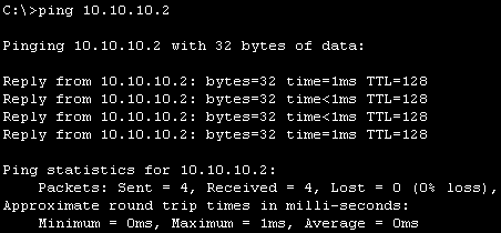
VLAN 간 통신 을 확인
-
pc1
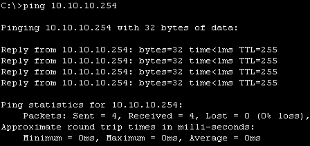
-
pc2
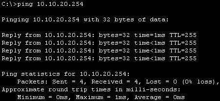
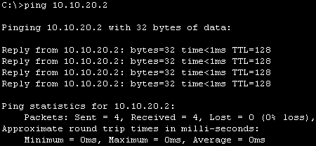
-
-
L3(DSW) 에는 설정을 안했는 Trunk 가 되는 이유
-
DTP(Dynamic Trunking Protocol)
DSW1#sh interfaces G0/1 switchport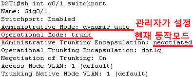
ASW1#sh interfaces g0/1 switchport
-
InterVLAN 설정 후 점검
-
L3 switch 가 라우터가 되도록 설정
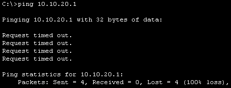
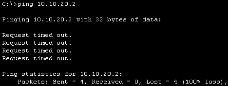
PC1] -> PC4]
ping 10.10.20.254 (O)
ping 10.10.20.1   (X)
ping 10.10.20.2   (X)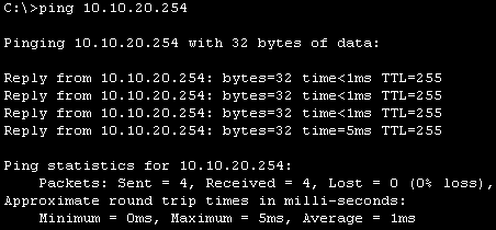
-
라우팅 테이블 확인
DSW1#sh ip route
-
라우터로 사용하도록 설정
DSW1(config)#ip routing
DSW1#sh ip route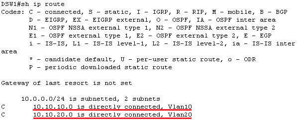
-
다시 통신 확인
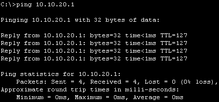
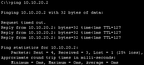
-
-
root switch(bridge) 를 확인
ASW1#sh spanning-tree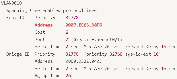

현재 Root ID = Bridge ID 같은 switch가 root bridge vlan 10, vlan 20 의 root bridge 가 같다
ASW2#sh spanning-tree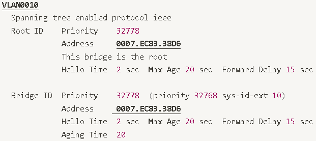
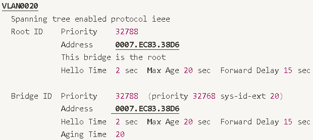
-
PVST 적용
-
VLAN 별 SpanningTree 를 관리하는 switch가 1개으로 VLAN 이 여러개인경우 root bridge 부하가 높다
-
vlan 별 root bridge 를 별도로 관리
-
ex)
vlan 10 의 root bridge asw1
vlan 20 의 root bridge asw2
-
switch 별로 우선순위 적용하여 root bridge 를 변경
ASW1(config)#spanning-tree vlan 10 priority 0 ASW2(config)#spanning-tree vlan 20 priority 0 -
바뀐 root bridge 확인
ASW1#sh spanning-tree
ASW2#sh spanning-tree
-
simulation mode 로 확인
각 통신 해당 VLAN root bridge를 먼저 거치는것을 확인 > 부하분산 (Load Balancing)
-
-
root switch 이중화
-
root bridge 공백시 대신할 swtich를 미리 지정
ASW1(config)#spanning-tree vlan 10 root primary
ASW2(config)#spanning-tree vlan 10 root secondary

ASW2(config)#spanning-tree vlan 20 root primary
ASW1(config)#spanning-tree vlan 20 root secondary
-
Link 이중화
- Link Aggregation(=Trunk)
-
여러 개의 물리적인 링크를 논리적인 하나의 링크로 사용하는 기술
-
목적
부하분산 → 속도 향상, 대역폭 증가
장애 우회 …
서버와의 연동 → 티밍(Teaming), 본딩(Bonding), …
-
관련 용어 → Link 집성, 트렁킹, 이더채널(cisco), NIC Teaming, Bonding …
-
타 벤더에서는 Cisco에서 Trunk Port/Access Port를 Tagged Port/UnTagged Port라고 부름
-
-
Port Tunkking 과 비교
-1668420756875-30.png)
-
Ether Channel
-
Cisco에서 지원하는 Link 이중화 기술
-
Link를 논리적으로 묶을 수 있음(LACP → 최대 8개, PAgP → 최대 16개)
소속 내 모든 포트는 포트모드가 같아야 함
소속 내 모든 포트는 대역폭과 전송 방식(Duplex)가 동일해야 함
소속 내 포트는 SPAN이면 안 됨
-
-
Ether Channel 설정 방식
-
Static(정적) 설정
관리자가 모든 설정을 직접 함
-
Dynamic(동적) 설정
Protocol을 이용하여 협상을 통해 설정 함 → LACP, PAgP
-
Port Channel 설정 시 묶은 후에 변경할 경우 각각 설정하는 것이 아닌 묶은 포트채널에서 설정
-
L2 etherchannel
-
구성도
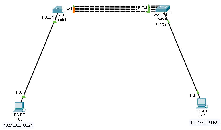
-
각 스위치별로 사용될 인터페이스 범위 입력
-
양쪽 스위치 동일
Switch(config-if-range)#interface range f0/1-4
-
-
etherchannel 협상시 사용할 프로토콜 지정 > 활성화
-
LAcP:Link Aggregation , 국제표준
-
PAgP:Port Aggregation , cisco 전용
-
논리적인 포트 생성 메시지를 확인
Switch(config-if-range)#channel-protocol lacp
Switch(config-if-range)#channel-group 1 mode active
-
새로운 인터페이스 진입
Switch(config)#interface port-channel 1 -
etherchannel 정보 확인
Switch#sh etherchannel summary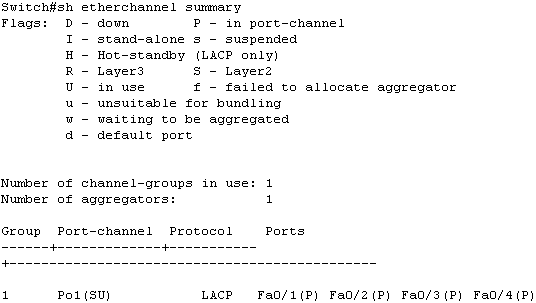
-
-
양쪽 통신 테스트
-
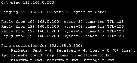
192.168.0.100] -> 192.168.0.200]
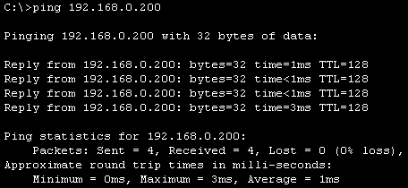
-
하나가 끊어져도 통신이 된다

-
L3 etherchaanel
-
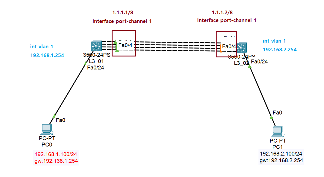
구성도
-
각 Switch별 SVI 를 설정
L3_01(config)#interface vlan 1 L3_01(config-if)#ip address 192.168.1.254 255.255.255.0 L3_01(config-if)#no sh L3_02(config)#interface vlan 1 L3_02(config-if)#ip address 192.168.2.254 255.255.255.0 L3_02(config-if)#no sh -
Port-channel 인터페이스 설정 - 양쪽 모두 동일
-
사용될 물리적 인터페이스의 범위 설정
L3_01(config)#int range f0/1-4 -
etherchannel 협상시 사용할 프로토콜 설정
L3_01(config-if-range)#channel-protocol lacp -
활성화
L3_01(config-if-range)#channel-group 1 moade active -
논리적 인터페이스 생성 메시지 확인

-
논리적 인터페이스 진입
L3_01(config-if-range)#int port-channel 1 -
논리 채널 인터페이스 확인
L3_01#sh etherchannel summary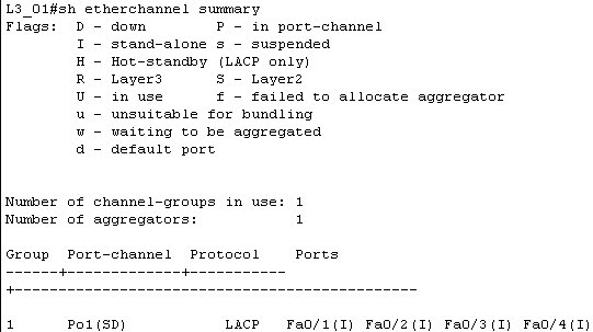
-
-
스위치별 인터페이스에 주소를 입력
L3_01(config)#interface port-channel 1 L3_01(config-if)#no switchport L3_01(config-if)#ip address 1.1.1.1 255.0.0.0 L3_01(config-if)#no sh L3_02(config)#int port-channel 1 L3_02(config-if)#no switchport L3_02(config-if)#ip address 1.1.1.2 255.0.0.0 L3_02(config-if)#no sh -
라우터 선언 및 라우팅 테이블 설정
L3_01(config)#ip routing
L3_01(config)#do sh ip routing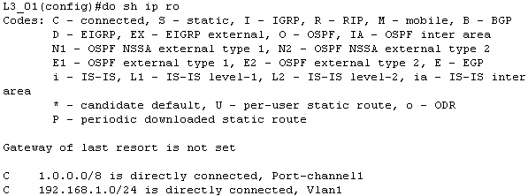
L3_02(config-if)#ip routing
L3_02(config)#do sh ip ro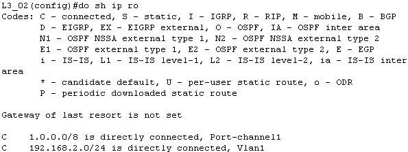
-
구간별 통신 체크
-
192.168.1.100]-> 192.168.1.254]
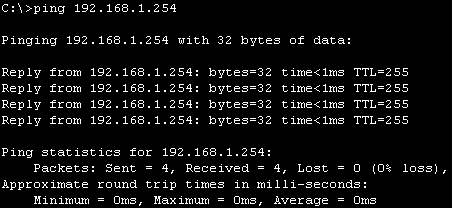
-
1.1.1.1]->1.1.1.2]

-
192.168.2.100]-> 192.168.2.254]
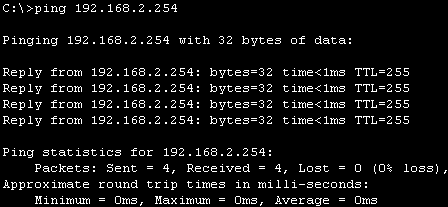
-
192.168.2.100]-> 192.168.2.100]
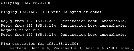
-
-
라우팅 테이블 설정 후 다시 통신 체크
L3_01(config)#ip route 192.168.2.0 255.255.255.0 1.1.1.2
L3_02(config)#ip route 192.168.1.0 255.255.255.0 1.1.1.1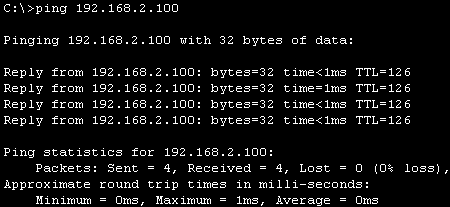
Teaming
-
구성도
-1668425850341-50.png)
-
어댑터 추가 인터페이스 기본 설정
-
ens32 (slave 인터페이스)
[root@localhost network-scripts]# vi ./ifcfg-ens32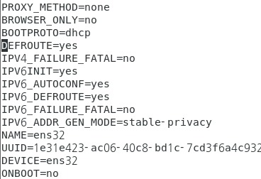
-
ens33 (slave 인터페이스)
[root@localhost network-scripts]# vi ./ifcfg-ens32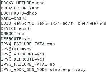
-
NetworkManager 다시 시작후 적용된 내용 확인
[root@localhost ~]# systemctl restart NetworkManager
[root@localhost ~]# nmcli connection
-
-
NetworkManager 상태 확인
[root@localhost ~]# systemctl status NetworkManager
-
어댑터 및 인터페이스 확인
[root@localhost ~]# ip link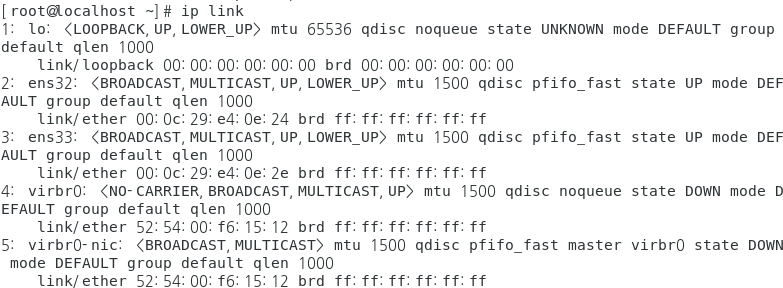
[root@localhost ~]# nmcli device status - 설정 가능한 mode
- activebackup : 기본적으로 사용할 active port 를 선택 하고 나머지는 backup - fail over 감시
- loadbalance : 트래픽 자체를 균등하게 분산
- LAcP : 802.3ad Link Aggregation
- brodcast : 모든 포트로 전송
- roundrobin : 포트별로 packet 를 번갈아가면서 전송
-
teaming 0 이라는 이름으로 master 인터페이스를 생성
[root@localhost ~]# nmcli con add con-name teaming0 type team ifname teaming0 config  '{ "runner":{"name":"activebackup","hwaddr_policy":"by_active"}, "link_wath":{"name":"ethtool","delay_up":2500,"delay_down":1000}, "ports":{"ens32":{"prio":-10,"sticky":true},"ens33":{"prio":100}}}'

[root@localhost ~]# nmcli connection show
-
ens32 , ens33 이름으로 slave 로 지정
-
ens32
[root@localhost ~]#nmcli connection add con-name teaming0-port1 type team-slave ifname ens32 master teaming0
-
ens33
[root@localhost ~]#nmcli connection add con-name teaming0-port2 type team-slave ifname ens33 master teaming0
[root@localhost ~]# nmcli connection show
-
-
teaming0 인터페이스에 주소 입력
# nmcli connection modify teaming0 ipv4.address 172.16.0.190/24 ipv4.gateway 172.16.0.254 ipv4.dns 203.248.252.2 ipv4.method manual connection.autoconnect yes -
slave > master 순으로 활성화
[root@localhost ~]# nmcli connection up teaming0-port1
[root@localhost ~]# nmcli connection up teaming0-port2
[root@localhost ~]# nmcli connection up teaming0
[root@localhost ~]# nmcli connection reload
[root@localhost ~]# nmcli connection show
-
teaming 확인
[root@localhost ~]# teamnl teaming0 ports
[root@localhost ~]# teamdctl teaming0 state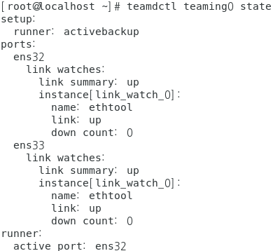
[root@localhost ~]# ifconfig teaming0
[root@localhost ~]# ping www.google.com
-
active-backup test
-
ping www.google.com 중간에 ens32 를 링크 끊는다
-
다시 확인
[root@localhost network-scripts]# teamdctl teaming0 state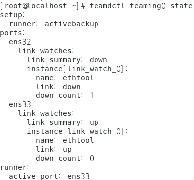
-
Gateway 이중화
- Router를 이용한 GW 이중화를 문제점
- Host에 할당된 default-gateway정보를 관리자가 직접 변경해야 함
-
Gateway 이중화
-
Router 장애를 대비하는 기술
-
일반적인 Router를 이중화 했을 때 발생하는 취약점을 프로토콜로 해결
-
Layer 3 Switch에서 지원 됨
FHRP(First Hop Redundancy Protocol) → HSRP/GLBP,/VRRP
-
FHRP(First Hop Redundancy Protocol)
-
FHRP의 기본 동작 방식
-
이중화 그룹을 생성하여 그룹을 대표하는 가상의 Interface를 생성함
-
그룹 인터페이스에 호스트에 할당할 gateway IP를 할당 → V-IP(Virtual IP)
-
이중화 그룹에서 주/보조 장비를GARP 결정하여 주 장비로 결정된 물리적인 Interface의 MAC을 전파 함
-
주 장비의 장애가 발생했을 때를 이용하여 새로운 주 장비(이전 보조 장비)의 MAC을 전파 함
호스트에 설정된 default-gateway IP는 그대로 유지되면서 MAC만 변경됨
MAC주소의 변경에 의해 gateway의 경로가 변경 됨
-
-
FHRP (First Hop Redundancy Protocol) 종류
-
HSRP(Hot Standby Router Protocol)
cisco에서 개발한 Gateway 이중화 프로토콜
-
GLBP(Gateway Load Balancing Protocol)
cisco에서 개발
이중화보다는 부하분산(load-balancing)을 목적으로 사용되는 프로토콜
-
VRRP(Virtual Router Redundancy Protocol)
IEEE에서 표준으로 제정한 프로토콜
-
VRRP
-
VRRP(Virtual Router Redundancy Protocol)
-
RFC 2338에 정의된 표준 프로토콜
-
특징
Multicast 주소 → 224.0.0.8
hello time → 1초, hold time → 3초
주 → master, 보조 → backup
-
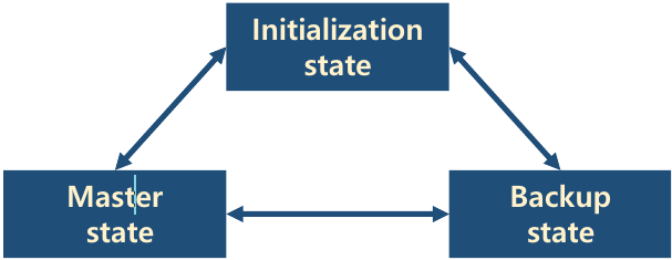
- VRRP 상태변화
- Init → 이중화 동작의 준비 상태
- Backup → init 다음 상태 또는 보조 장비 상태
- Master → 주 장비 역할을 수행하는 상태
- VRRP Track
-
Tracking → 상태를 추적하는 행위
-
주 역할을 수행하는 Master 장비의 Uplink에 대한 장애를 반영하는 기능
-
동작 순서
다양한 조건을 이용하여 Tracking 수행 정책을 설정 함
Tracking 정책에 일치하는 상황이 발생하면 Master 장비의 우선순위를 자동으로 Backup 장비보다 낮게 감소 함 → 우선순위 값 계산을 주의 해야 함
협상에 의해 Backup 장비가 Master로 변경 됨
-
Preempt설정을 함께 사용 함
-
-
VRRP Preempt
-
장비의 장애가 복구되면 기존의 역할을 복구하는 기능
Master 장비의 장애가 발생하면 Backup 장비가 Master가 됨
기존 Master 장비의 장애가 복구 되어도 변경된 역할이 복구되지 않음
-
Preempt 기능이 수행되면 초기 우선순위 값으로 자동 설정되어 기존의 역할을 되돌려 받게 됨
-
실습
-
구성도
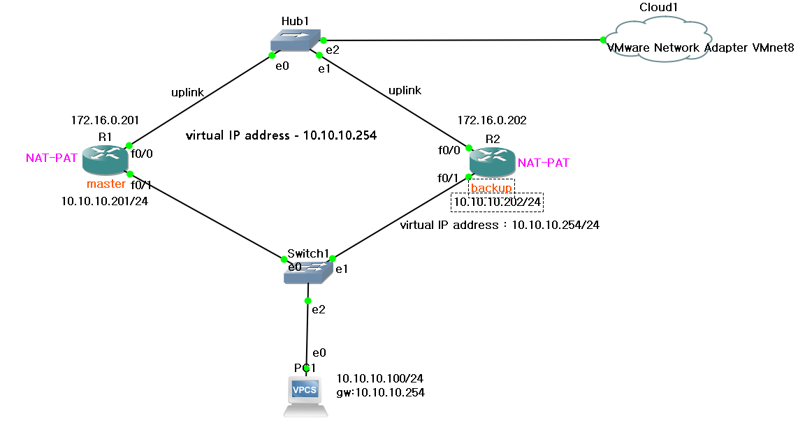
-
pc 주소 입력하면서 wireshark로 gARP 확인
PC1> ip 10.10.10.100 255.255.255.0 10.10.10.254
PC1> sh

-
각 라우터에 인터페이스 설정
R1(config)#int f0/0 R1(config-if)#ip address 172.16.0.201 255.255.255.0 R1(config-if)#no sh R1(config)#int f0/1 R1(config-if)#ip address 10.10.10.201 255.255.255.0 R1(config-if)#no sh R2(config)#int f0/0 R2(config-if)#ip address 172.16.0.202 255.255.255.0 R2(config-if)#no sh R2(config)#it f0/1 R2(config-if)#ip address 10.10.10.202 255.255.255.0 R2(config-if)#no sh -
구간별 통신 체크
-
PC1> ping 10.10.10.201

-
PC1> ping 10.10.10.202

-
R1#ping 172.16.0.254

-
R2#ping 172.16.0.254

-
-
VRRP
Master 설정
-
Virtual IP Adddress
R1(config)#int f0/1 R1(config-if)#vrrp 1 ip 10.10.10.254 -
우선순위 설정
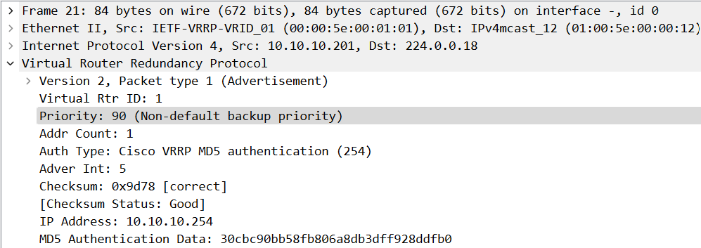
R1(config-if)#vrrp 1 priority 120 -
5초 마다 체크
R1(config-if)#vrrp 1 timers advertise 5 -
Tracking 정책 : Uplink 모니터링
R1(config)#track 1 interface fastEthernet 0/1 line-protocol -
Tracking 중 문제발생시 우선순위 를 감소
R1(config-if)#vrrp 1 track 1 decrement 30 -
최소 5초후에 변경과정 활성화
R1(config-if)#vrrp 1 preempt delay minimum 5 -
master-backup 간 인증키
R1(config-if)#vrrp 1 authentication md5 key-string 0 aaa
Backup 설정
-
Virtual IP Adddress
R2(config)#int f0/1 R2(config-if)#vrrp 1 ip 10.10.10.254 -
우선순위를 Master 보다 낮게 설정
R2(config-if)#vrrp 1 priority 100 -
Master의 타이머값 그대로 사용
R2(config-if)#vrrp 1 timers learn -
인증키 설정
R2(config-if)#vrrp 1 authentication md5 key-string 0 aaa
-
-
구간별 통신 체크
-
10.10.10.100 → 10.10.10.254

-
arp 캐시 확인

-
-
VRRP 정보 확인
-
R1
R1# sh vrrp all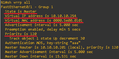
-
R2
R2# sh vrrp all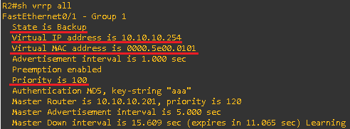
-
-
inside link 변화 확인
-
링크가 끊어지는 경우 G/W 의 변화
-
Master 로 가는 링크를 임시 삭제
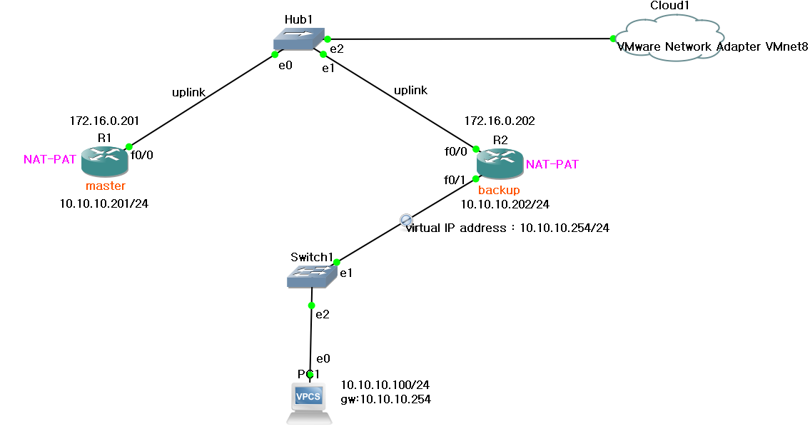
-
gARP가 발생한다
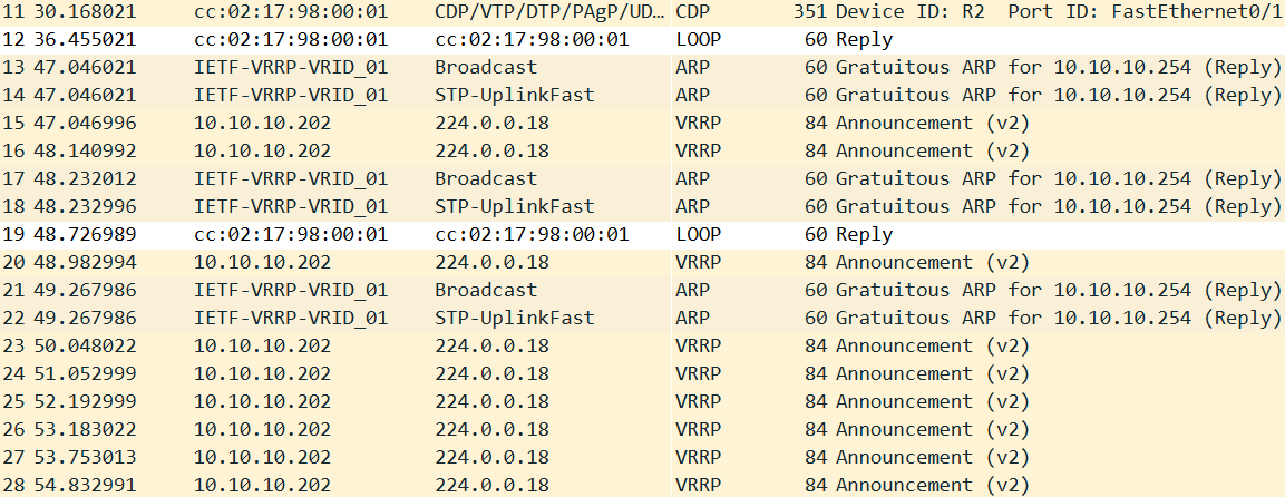
-
ping 테스트 후 arp 체크
PC1> ping 10.10.10.254
PC1> arp
-
-
uplink의 변화(outside 쪽 link)
-
VRRP 확인
# sh vrrp brief

-
NAT-PAT 설정
Master : R1 R1(config)#access-list 1 permit 10.10.10.0 0.0.0.255 R1(config)#int f0/0 R1(config-if)#ip nat outside R1(config-if)#int f0/1 R1(config-if)#ip nat inside R1(config)#ip nat inside source list 1 interface f0/0 overload Backup : R2 Backup:R2] R2(config)#access-list 1 permit 10.10.10.0 0.0.0.255 R2(config)#int f0/0 R2(config-if)#ip nat outside R2(config-if)#int f0/1 R2(config-if)#ip nat inside R2(config-if)#exit R2(config)#ip nat inside source list 1 interface f0/0 overload -
통신 체크
PC1> ping 8.8.8.8
-
통신이 안되는 이유 -> default route 설정을 하지 않았기 때문이다
-
default route 설정
R1(config)#ip route 0.0.0.0 0.0.0.0 172.16.0.254 R2(config)#ip route 0.0.0.0 0.0.0.0 172.16.0.254 -
다시 통신 체크
PC1> ping 8.8.8.8
-
-
Master의 interface를 shutdown
-
R1

-
R2

-
PC1> ping 8.8.8.8

-
-
Master의 interface 를 no shutdown
-
R1

-
R2


-

댓글 남기기